When a temporary isolation unit goes live in minutes—not days—the door seam is where success or failure shows first. This guide walks you, step by step, through selecting materials, RF/HF welding airtight zippers into TPU/PU‑coated fabrics, and proving air‑retention with pressure‑hold (pressure‑decay) testing. It’s written for engineering, QA, and field commissioning teams who need procedures that stand up to audits and real‑world handling. Disclaimer: this is manufacturing/engineering guidance, not clinical advice; where acceptance criteria are adapted from analogous standards, that is stated explicitly and should be validated in your DVP&R.
Key takeaways
- Pair polyether‑TPU–coated polyester substrates with weldable‑TPU zipper flanges for better hydrolysis resistance in warm, humid hospital conditions (Covestro healthcare TPU overview).
- Use RF/HF welding (typ. 27.12 MHz class) to fuse the zipper’s TPU flange to the coated fabric; target a fused lap width of 20–30 mm at door openings for strength and sealing continuity (Erez on HF welding).
- Build your RF process window with documented trials: set clamp pressure, dwell/time, and cooling under pressure to achieve full fusion without print‑through; confirm with peel/shear coupons per coated‑fabric practice.
- Verify mechanics with coated‑fabric seam tests from ASTM D751 and tensile checks near the welded flange per ISO 1421 (overview) before leak testing (ASTM D751 overview; ISO 1421 index).
- Factory pressure‑hold (adapted): 1.20–1.25× nominal operating pressure, 30‑minute hold, ≤5% drop, no continuous bubbles at seams/zipper. Field check: ~1.10× nominal, 10–15 minutes, ≤3% drop. These thresholds are clearly labeled adaptations from the U.S. Coast Guard RHI practice (USCG WI 07(03)%20-%20Certification%20of%20Rigid%20Hull%20Inflatable%20(RHI)%20Vessels.pdf)).
RF welding airtight zippers for medical isolation tents — intended use and scope
This guide focuses on RF welding airtight zippers into rapidly deployable field hospitals and medical isolation modules—particularly doorways, vestibules, and access ports that experience frequent ingress/egress and must maintain tight air control. Alternatives like hot air/hot wedge welding and reactive/solvent adhesives are acknowledged but not covered in depth; they can play roles for materials that are hard to RF‑weld or for localized repairs.
Audience: process/RF technicians, industrial designers, SQEs, and field service teams. Outputs: practical SOPs, acceptance criteria, and traceable documentation practices for a clean, auditable build.
Fundamentals of RF/HF welding for TPU-/PU-coated fabrics
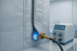
RF/HF welding heats polar thermoplastics (e.g., TPU, PU) volumetrically through dielectric loss, producing uniform fusion across thickness with crisp heat‑affected zones. It’s favored for sealed textile structures because it avoids needle holes and provides repeatable, monolithic seams. Typical industrial systems operate in the 27.12 MHz ISM band with brass or aluminum electrodes on a pneumatic press. For an accessible primer, see the technology overviews from Weldmaster and Erez Therm.
Here’s the deal: stitch a zipper and you create hundreds of potential leak paths; RF‑weld a weldable TPU flange and you fuse polymer to polymer, closing those paths entirely.
Selecting zippers and substrates
- Substrate choice: For hospital environments with humidity, heat, and aggressive cleaning, pair polyester base fabrics coated with polyether‑grade TPU for superior hydrolysis resistance. Confirm sterilization and cleaning compatibility (e.g., VHP, ETO, gamma) on supplier datasheets such as Covestro’s healthcare TPU and Lubrizol’s Medical Device TPU Guide.
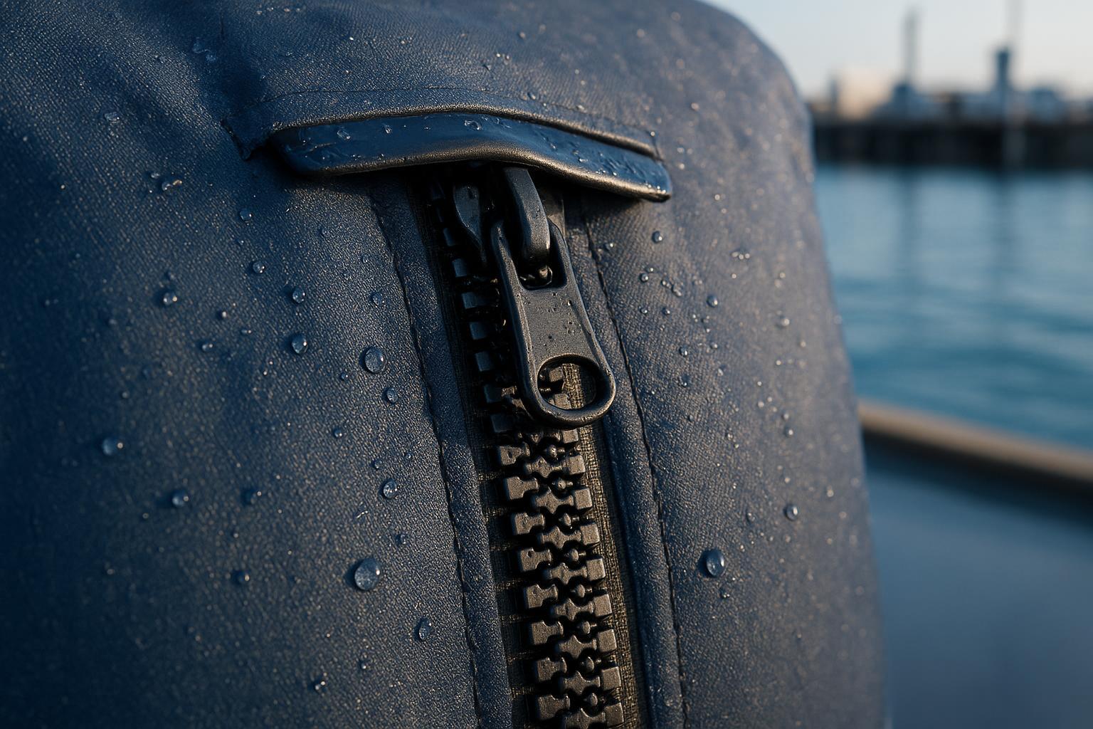
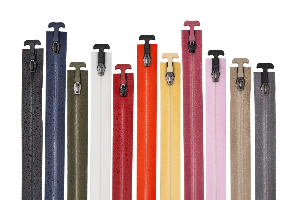
- Zipper geometry: Favor airtight zippers with wide, integrated weldable TPU flanges that allow single‑ or double‑lap joints and distribute stress along the door path. A neutral example is a U‑channel‑style flange as seen in airtight zippers with weldable TPU flanges on the U‑Channel AeroSeal Airtight Zipper; integrating a weldable flange helps avoid stitch‑related leak paths. (Neutral reference; validate geometry against your design.)
- Slider and chain options: For high‑cycle doors, dual‑slider or dual‑track variants can support bidirectional access or redundancy; evaluate mass, stiffness, and ease of decontamination.
Joint design and fixturing for door openings
Aim for a fused lap width of 20–30 mm along primary entry seams (actual width depends on fabric weight, load path, and door geometry). Keep end radii generous to reduce stress concentration and thermal edge effects. Add reinforcement doublers at corners and slider parking zones. Use mechanical guides or fixtures to keep zipper rails/teeth out of the electrode pinch and to maintain symmetric clamp pressure.
Before stepping down to H3 details, validate the door path in CAD and on scrap panels to confirm bend radii, flange lay, and slider clearance through the welded zone.
Fixturing notes
- Electrode bars should include radiused terminations to avoid hotspots.
- Consider heat sinks or RF masks near stops/sliders to prevent local overheating or print‑through.
- Ensure flat, debris‑free support surfaces; even small particles can telegraph defects into the bond line.
RF process development and controls
Treat process development as a controlled experiment with a trial matrix. Start with the RF equipment vendor’s TPU presets, then iterate.
- Parameters to tune: clamp pressure, dwell/time, power setting, and cooling under pressure. Seek full polymer fusion with minimal print‑through and no embrittlement.
- Coupon validation: Cut peel/shear coupons from the welded zipper‑flange zone. Benchmark strength against base fabric per coated‑fabric practice—use the seam/bond sections in ASTM D751 and tensile testing across the weld per ISO 1421 (prepare coupons with the weld centered in the gauge length). For a brand‑documented near‑bond tensile recommendation, see ZIZIP’s note on tensile tests near zipper bonds.
- Documentation: Record electrode geometry, stack‑up, environmental conditions, and instrument calibration. Lock parameters with revision control when acceptance is met.
Think of the process window like a runway: too little energy and you never lift off (incomplete fusion); too much and you overshoot into scorching or brittle zones. Stay centered and cool under pressure before releasing the part.
Pressure-hold (pressure-decay) leak testing — acceptance criteria and SOP
Pressure‑hold (pressure‑decay) is the most audit‑friendly way to verify air‑retention in large, flexible volumes. The principle is simple: pressurize, isolate, stabilize, and monitor decay versus a threshold.
- Factory type test (adapted, validate in DVP&R):
- Setpoint: 1.20–1.25× the nominal operating pressure of the target compartment.
- Duration: Hold 30 minutes after stabilization.
- Acceptance: ≤5% pressure drop over the hold; no continuous bubbling at seams/zipper interface during targeted soapy‑water spray localization.
- Disclosure: These values are an adaptation from rigid‑hull inflatable (RHI) collar practice in USCG WI 07(03)%20-%20Certification%20of%20Rigid%20Hull%20Inflatable%20(RHI)%20Vessels.pdf).
- Field commissioning/maintenance (rapid check):
- Setpoint: ~1.10× nominal.
- Duration: 10–15 minutes.
- Acceptance: ≤3% pressure drop; no bubble indications.
- If failed: Isolate by section, repeat; immersion only for removable subassemblies.
- Instrumentation and uncertainty management:
- Stabilize temperature to avoid adiabatic cooling artifacts. Allow a short stabilization period after pressurization before timing the test.
- Use differential pressure instruments suitable for large volumes (e.g., LV‑class testers) and enable environmental compensation when available. See the MFE leak‑testing primer for method context and ATEQ documentation for LV‑class instrumentation features.
- Document ambient temperature/relative humidity and gauge calibration in the test log.
SOP outline (pressure-hold)
- Inspect all valves, seams, and the zipper track for visible defects; record serials and instrument calibration IDs.
- Pressurize the module to the setpoint; isolate and allow temperature stabilization.
- Start the timed hold; log pressure at defined intervals (e.g., 0, 5, 10, 20, 30 min).
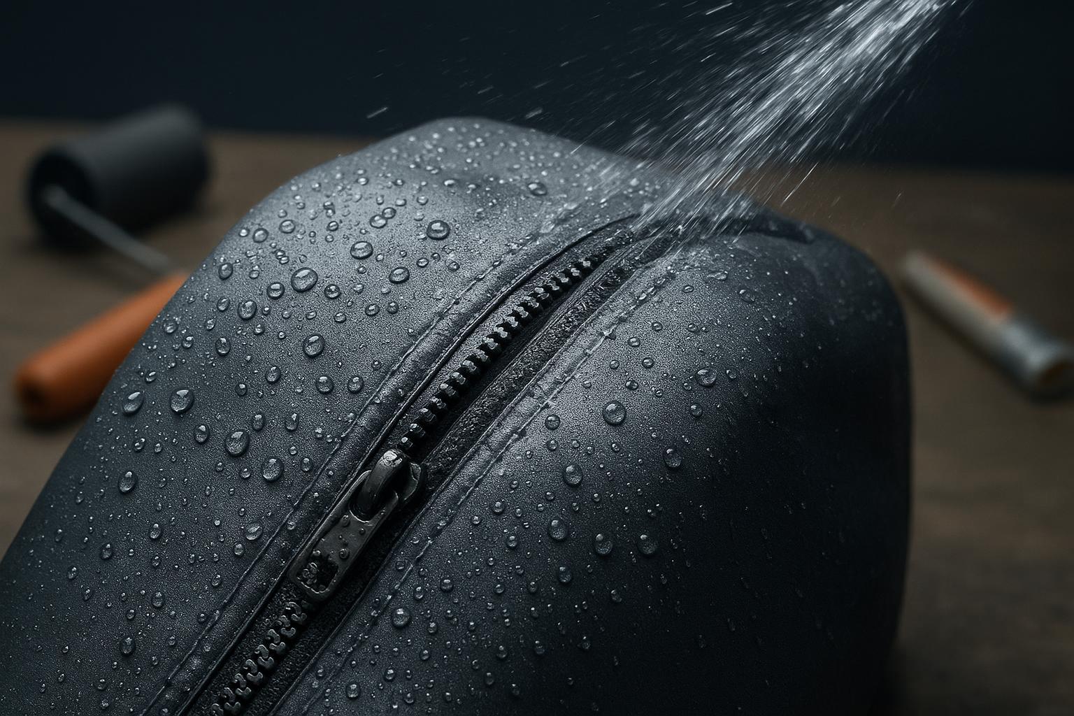
- If decay exceeds the threshold, localize with a targeted soapy‑water spray; repair per rework SOP and re‑test.
- Archive results with ambient conditions and revisioned SOP references.
Field commissioning, repairs, and maintenance cadence
For commissioning, use the 10–15 minute rapid check at ~1.10× nominal. For periodic maintenance, align with site policy and usage intensity (e.g., weekly checks during deployments with high door cycles). Minor defects (edge voids, scuffs) may be reworked with localized RF patches using matching TPU films and controlled fixtures. Always document rework and run a shortened pressure‑hold confirmation.
Troubleshooting: from visual defects to root causes
- Edge scorching or print‑through: Excessive energy density or poor heat sinking near ends. Remedy: reduce dwell/increase cooling; add radiused terminations or masks.
- Voids/poor fusion streaks: Contamination or insufficient clamp pressure. Remedy: improve cleaning and lint control; raise pressure incrementally.
- Slider binding post‑cooling: Misalignment or flange distortion. Remedy: re‑fixture with mechanical guides; verify symmetric pressure and full cooling under load.
Practical micro‑example: welding a TPU‑flanged airtight zipper into a negative‑pressure vestibule
Context: A vestibule panel in a modular isolation unit requires a vertical door with frequent bi‑directional access. The team selects a polyether‑TPU–coated polyester fabric and an airtight zipper with a wide, weldable TPU flange. The joint is a single‑lap weld targeting 25 mm fused width, with corner doublers and a slider parking pad.
Workflow (abridged):
- Prep and fixture: Clean with TPU‑compatible wipes; glove handling. Fixtures keep zipper rails out of the electrode line; electrode ends are radiused.
- Parameter development: Starting from vendor TPU presets (27.12 MHz class), the team iterates clamp pressure and dwell to eliminate faint fusion streaks. Cooling is maintained under pressure for consistent crystallization.
- Verification: Peel/shear coupons from the welded flange meet internal minima based on ASTM D751 seam tests, and tensile coupons across the weld per ISO 1421 retain the required strength fraction.
- Leak test: Factory type test at 1.25× nominal, 30 minutes, records ≤5% pressure drop with no bubble indications along the zipper interface. The acceptance is documented as an adaptation referencing USCG WI 07(03)%20-%20Certification%20of%20Rigid%20Hull%20Inflatable%20(RHI)%20Vessels.pdf).
Result: A smooth‑running door seam with traceable RF parameters, mechanical validation, and a clean pressure‑hold log—ready for commissioning.
References and further reading
- RF/HF welding fundamentals and coated textiles: Weldmaster RF welding technology; Erez Therm HF welding introduction.
- Coated‑fabric test families: ASTM D751 overview; ISO 1421 overview.
- Leak‑testing concepts and instrumentation: MFE leak‑testing primer; ATEQ F620LV overview.
- Acceptance analog and disclosure: U.S. Coast Guard WI 07(03) — RHI collars%20-%20Certification%20of%20Rigid%20Hull%20Inflatable%20(RHI)%20Vessels.pdf).
- Internal reading for geometry and near‑bond testing notes: U‑Channel AeroSeal Airtight Zipper; tensile tests near zipper bonds; TPU‑coated tape properties.