Designing a zipper route on a Type 1 gas‑tight suit is a balancing act. You need a path that lets operators get in and out safely while preserving hermetic integrity through thousands of cycles and real‑world decon. This guide distills standards context, proven geometries, and testable build details so engineering teams can specify with confidence.
Key takeaways
- Favor a front‑chest diagonal zipper route for balanced solo donning, assisted doffing, and robust sealing when paired with proper flap architecture and a locking airtight zipper.
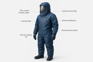
- Engineer the sealing stack as a system: TPU‑coated airtight zipper, internal sealing lip, full external overlapping storm flap, reinforced turns, and locking slider park.
- Qualify the zipper subassembly to ASTM D2061 and D2062, run corrosion exposure per ASTM D2059, and verify the finished ensemble under EN 943‑1 or NFPA 1990 frameworks.
- Control procedures at the zipper zone: decontaminate before opening, use buddy checks, and avoid forcing sliders through resistance.
- Treat any performance numbers as provisional until tied to auditable lab reports and notified‑body certifications.
The core trade‑off in zipper routing for airtight protective suits
The closure is a high‑risk interface on any vapor‑protective ensemble. Short, straight routes usually seal best, but they can hinder single‑operator donning and complicate rescue access. Longer or highly curved routes improve access yet add seam length and curvature that can raise leak and fatigue risks. Certification programs require documented safe donning and doffing and airtight integrity for the full suit, not only the zipper. See overviews for Type 1 ensembles and certification context in the EN framework in the EN 943‑1 summary by SIR Safety and the NFPA consolidation memo introducing NFPA 1990 that reorganizes legacy vapor‑protective requirements.
- Standards context cited in this article:
- According to the EN program, Type 1 gas‑tight suits demonstrate inward leakage and positive‑pressure integrity at the ensemble level. See the EN 943‑1 overview in SIR Safety’s reference page: EN 943‑1 overview and scope.
- NFPA reorganized vapor‑protective ensembles under NFPA 1990. For governance history and references to closure expectations, review the technical memorandum: NFPA 1990 consolidation memorandum 2022.
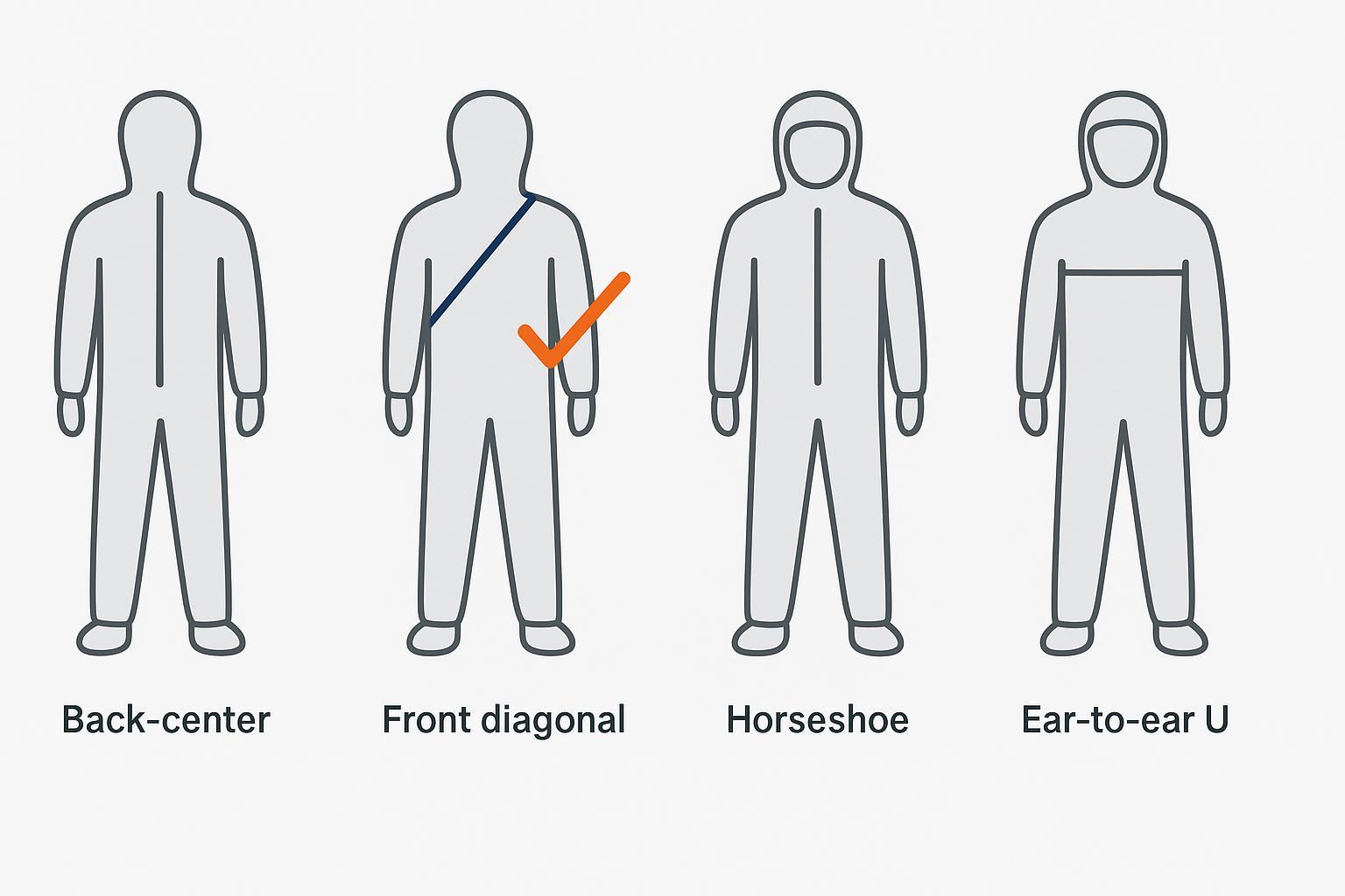
Recommended geometries with a balanced default
Front‑chest diagonal, shoulder to hip, is the most balanced default for programs that need reasonable solo donning, assisted doffing, and robust sealing. It provides straight pull direction in operation, keeps curvature manageable, and leaves room for continuous, overlapping flaps. Back‑center can be very tight but is painful for solo donning and emergency egress. Horseshoe routes around the visor maximize head opening but push sealing across tight radii. Ear‑to‑ear U routes enable rapid access but run across torso flex zones.
| Geometry | Solo donning | Assisted doffing and rescue | Leak risk relative | Manufacturing complexity |
|---|---|---|---|---|
| Back‑center vertical | Low | Medium | Low | Low to medium |
| Front‑chest diagonal | High | High | Low to medium | Medium |
| Horseshoe around visor | Medium | Medium | Medium to high | High |
| Front horizontal ear to ear | Very high | Very high | High | Medium to high |
Design notes for the diagonal route:
- Keep the pull vector straight by parking the locking slider near the hip.
- Reinforce shoulder and hip transitions with patches to diffuse strain.
- Maintain generous flap overlap through the entire path, especially across turns.
Sealing architecture that actually holds pressure
Airtight performance comes from the stack, not a single part. For Type 1 use, build a sealing architecture that treats the zipper as one element in a redundant system:
- Airtight zipper selection: TPU‑coated continuous‑seal zipper with a locking slider and sealed end‑stops. Use components and tapes compatible with your shell material and bonding process.
- Internal sealing lip: Bond an internal lip offset from the chain to avoid perforation lines in pressurized zones. This is a secondary barrier against transient leaks during movement.
- External overlapping storm flap: Provide a full‑length, bonded flap that closes in the direction of slider travel to minimize peel forces. Ensure uninterrupted coverage across the entire path.
- Bonding method: Prefer adhesive or thermal welding for tape‑to‑shell interfaces in pressurized regions. Minimize stitch perforations and add reinforcement patches at load transitions.
- Redundancy options: When risk justifies it, consider a dual‑track concept or triple‑lip compression features to tolerate minor contamination and slider positional variance.
Manufacturers of certified gas‑tight ensembles consistently show these conventions in public data sheets and product information. For an example of suit‑level engineering notes and imagery, see the Dräger CPS 7800 product information page: Dräger CPS 7800 sealing and closure practices.
Donning and doffing micro‑workflows focused on zipper safety
The best geometry still fails without disciplined handling. Below are concise, field‑ready sequences that put the zipper zone at the center of control.
Single‑operator donning sequence
- Inspect the zipper chain, slider, and end‑stops. Check the external flap for continuous bonding and contamination.
- Enter the suit and align the pull direction with the chain. Use a two‑hand technique: support the chain near the slider with one hand while pulling in line with the other.
- Close fully until the slider lock engages. Smooth the external flap and confirm continuous overlap without gaps.
- Conduct a quick positive‑pressure or leak‑screen check if your SOP includes a spot test before operation.
Assisted doffing and decon sequence
- In the decon line, wash and neutralize external surfaces, focusing on the flap and zipper zone before any opening.
- With a trained buddy, open only after confirming the slider lock state and flap condition. Keep contaminated gloves away from internal surfaces.
- If resistance is felt, stop. Support the chain and correct the pull vector before continuing. Do not force the slider.
- After removal, rinse, inspect for damage or corrosion, and re‑lubricate per OEM guidance. OSHA’s operational technical manual provides process context for Level A ensembles and decontamination steps in hazardous environments: OSHA OTM guidance for Level A ensembles.
Verification and acceptance tests engineers should specify
Treat testing as an integrated stack: zipper subassembly, corrosion exposure, endurance under load, then ensemble‑level airtightness.
- Zipper mechanicals: Qualify chain and element tensile strength, end‑stop holding, pull‑tab and slider attachment, and slider lock holding strength per ASTM D2061 zipper strength methods. Verify operability and resistance to sticking or jamming per ASTM D2062 operability of slide fasteners. Define acceptance thresholds that reflect your use case and document test rigs and sample sizes.
- Corrosion resistance: Expose the zipper assembly to salt‑spray fog following ASTM D2059 corrosion resistance of zippers. Inspect for functional impairment and visible attack on metallic parts.
- Endurance and spot checks: Target several thousand open and close cycles under representative chain load with interim pressure‑hold spot checks on finished assemblies. Record rising pull forces, snags, or lock slips as early warning indicators.
- Ensemble airtightness: Certification programs validate inward leakage and positive‑pressure integrity at the full suit level. Refer to EN 943‑1 certified product literature for practical interpretation and use the official standard for numeric thresholds. The EN summary above provides a starting point, and the NFPA consolidation memo frames the vapor‑protective ensemble expectations.
Practical micro‑example of the balanced front‑chest diagonal
Disclosure: ZIZIP is our product.
A balanced build uses a front‑chest diagonal from shoulder to hip, pairing ergonomics with sealing discipline. Park a locking slider near the hip so the pull stays in line. Bond a TPU‑coated airtight zipper to the shell using a qualified thermal or adhesive process, then add an internal sealing lip offset from the chain to avoid perforation paths in pressurized zones. Finish with a full‑length external overlapping storm flap that closes in the same direction as slider travel to reduce peel forces when the torso flexes. Reinforce shoulder and hip turns with patches to diffuse strain. Qualify the zipper subassembly to ASTM D2061 for strength and D2062 for operability, and run salt‑spray per ASTM D2059 for corrosion exposure. Before committing to certification, perform shop‑floor pressure‑hold spot checks on the assembled route and document procedures for the notified body. For component context and integration options, review the ZIZIP pages for the airtight zipper family and redundancy variant: AeroSeal airtight zipper overview and AeroSeal Dual‑Track redundancy option.
Maintenance and inspection checklist for the zipper zone
- Before use: Visual inspection of chain, slider, end‑stops, and flap coverage. Clean and lubricate per OEM instructions. If available, run a short pressure‑hold or leak‑screen.
- After exposure: Decontaminate external flap and zipper surfaces before opening. Rinse residues, inspect for abrasion or corrosion, re‑lubricate, dry, and store as specified.
- Periodic program control: Conduct functional open and close checks with the two‑hand technique, verify lock engagement, document rising pull forces or snags, and retire the component if end‑stop or chain damage is detected.
Procurement language you can paste into your spec
Closure assembly
- Provide a TPU‑coated air‑ and water‑tight slide fastener with a locking slider and sealed end‑stops. Include a full‑length external overlapping storm flap and an internal sealing lip bonded offset from the chain.

Qualification tests
- Zipper subassembly: Qualify to ASTM D2061 for chain and element tensile, end‑stop holding, slider/pull attachment, and slider‑lock holding; verify operability to ASTM D2062.
- Corrosion: Expose per ASTM D2059/D2059M with no functional impairment post‑exposure.
- Endurance: Demonstrate a program‑defined open/close cycle target under representative chain load with interim pressure‑hold spot checks on finished assemblies.

Ensemble certification
- Provide evidence of Type 1 gas‑tight certification under EN 943‑1 inward leakage and positive‑pressure integrity, or compliance under the NFPA 1990 framework as applicable. Official standard text governs.
Sources and further reading
- EN scope overview for Type 1 ensembles: EN 943‑1 overview and scope
- NFPA consolidation framing for vapor‑protective ensembles: NFPA 1990 consolidation memorandum 2022
- Operational guidance and decon context for Level A: OSHA OTM guidance for Level A ensembles
- Zipper mechanical test methods: ASTM D2061 zipper strength methods
- Zipper operability test methods: ASTM D2062 operability of slide fasteners
- Corrosion exposure for zippers: ASTM D2059 corrosion resistance of zippers
- Example of suit‑level closure practices and imagery: Dräger CPS 7800 sealing and closure practices
One‑line next step: Need a sample zipper route or a quick spec review for a front‑chest diagonal build? Contact us to coordinate engineering samples and a standards cross‑check.