Designing an encapsulated protective suit is a constant balancing act: users want fast, intuitive donning and doffing, while engineering demands a closure that remains gas-tight under pressure, movement, and abuse. This guide is written for protective-suit OEM product and structural engineers who must prioritize sealing reliability over convenience, specifically for the slanted chest-to-hip zipper route. We’ll translate standards into acceptance criteria, unpack route-specific failure modes, and provide implementable design rules you can take to CAD, the cutting table, and the pressure-test bench. Where evidence is limited, we’ll call it out and recommend how to validate.
By the end, you’ll have a practical playbook for zipper route sealing for encapsulated protective suits: how to model the sealing risks of a slanted chest-to-hip path, what tolerances and geometries to start with, and how to qualify the design using ISO and EN methods and, where relevant, NFPA’s dynamic testing.
Key takeaways
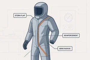
- Target geometry: maintain inside bend radius ≥30–40 mm along the slanted path; avoid compound bends near the slider park. Use reinforcement/backing strips at transitions.
- Flap architecture: plan for dual flaps with at-rest overlap of 20–30 mm and locking tabs at both terminations to sustain preload under pressure.
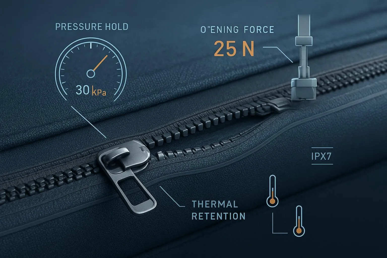
- Acceptance criteria: for whole-suit internal pressure testing (ISO 17491-1 Method 2), hold 1650 Pa for 6 minutes with ≤300 Pa drop; verify again after 2,000–10,000 slider cycles.
- Termination engineering: extend tape tails ≥20–25 mm beyond last tooth; RF weld to shell with ≈25×50 mm TPU-backed reinforcement patches; avoid exposed stitch lines across the pressure boundary.
- Verification plan: combine batch Method 1 (1000 Pa, 4 min, ≥800 Pa) with sampling to Method 2, plus periodic durability cycling and optional MIST for NFPA 1991.
Standards and verification methods that govern zipper route sealing for encapsulated protective suits
Engineers need measurable, auditable tests to prove zipper route sealing for encapsulated protective suits. Three pillars typically apply:
- EN 943-1/-2 for gas-tight chemical protective suits define performance and verification, with Type 1 suits requiring whole-suit leak-tightness via static internal pressure. A public listing for EN 943-2:2019 clarifies scope and structure while the full text remains paywalled; align your design dossier accordingly, and trace closure integrity to the whole-suit test regime outlined in the standard’s annexes and references. See the EN 943-2 listing on iTeh for scope context: EN 943-2:2019 overview and sample pages.
- ISO 17491-1 internal pressure tests are widely used in industry instructions. Method 2 (more rigorous) inflates, stabilizes, and then holds the suit at 1650 Pa for 6 minutes, passing if the pressure drop is ≤300 Pa. Manufacturer instructions mirror these parameters, such as the Lakeland pressure test kit data sheet and DuPont pressure test instructions.
- NFPA 1991 certification in the US emphasizes dynamic inward leakage assessment via MIST (Man-in-Simulant Test). For planning and terminology, see the IAFC guide to CBRN PPE selection and testing.
A note on in-service modeling: comparative analyses indicate typical in-service static internal pressures around a few hundred pascals for gas-tight suits; one peer-reviewed comparison notes about 400 Pa as a practical limit in use. Use these numbers to size flap preload and assess zipper path forces during motion while keeping formal acceptance bound to ISO/EN tests.
Why choose the chest-to-hip slanted route and what it changes for sealing
The slanted chest-to-hip route exists for good reasons. It creates a long, accessible opening that improves self-donning and allows a cleaner ingress path around rigid components like chest plates or harness hardware. It can also position the slider park in a protected zone away from helmet seals.
But this geometry makes sealing harder in three ways. First, the route is longer, so there’s more chain length and more potential points for micro-gapping. Second, the slant introduces asymmetric load paths: under internal pressure, the garment fabric tends to bias tension toward the lower hip, which can peel at bends or termini. Third, the slider park often sits near a region of frequent motion, compounding wear and backflow risk.
Think of the zipper like a pressurized gasketed seam with a built-in discontinuity at the slider and both ends. The slanted path forces that gasket to traverse curvature while the suit balloons. Lower curvature (larger radius) reduces local peel stress on TPU bonds and helps flaps stay seated. Your design’s job is to minimize stress concentrators and add redundancy so that even when the primary chain sees micro-gaps, the internal/external flaps elongate the leakage path enough to pass Method 2 before and after durability cycling.
FMEA for the slanted chest-to-hip route
Below is a route-specific failure-mode table. Where numeric guidance isn’t mandated by a standard, the mitigation is framed as an engineering rule to be validated through qualification tests.
| Failure mode | Likely cause | Detection method | Primary mitigation | Verification test |
|---|---|---|---|---|
| Slider backflow near park | Non-locking slider, tolerance stack, debris | Pressure-decay shows localized hiss at slider end | Use locking slider with gasketed saddle; define a parking SOP; add internal flap baffle | ISO 17491-1 Method 2 pre/post cycle, leak mapping during hold |
| Termination edge leakage | Weak weld at stop, exposed stitching, short tape tails | Bubbles/dye at ends; pressure drop early in hold | Welded stops; extend tape tails ≥20–25 mm; 25×50 mm reinforcement patches | Method 2; dye-penetration on ends |
| Bend-crease leakage | Tight radius <30 mm; repeated flex | Pressure-decay after bending cycles; visual crease lines | Maintain R≥30–40 mm; add formed backing strips at transitions | Post-cycle Method 2; motion simulation |
| Tape-to-panel delamination | Incompatible TPU, thermal cycling, chemical exposure | Peel tests; visible edge lift | RF weld or heat lamination with compatibility confirmation; perimeter bead in critical zones | Peel test + Method 2; chemical-aging then re-test |
| Stitch-hole leaks | Stitching across pressure boundary | Immediate bubbles at stitch line | Avoid stitching; if unavoidable, fully encapsulate with weld/tape | Method 2 with local leak check |
| Slider wear-induced leakage | Cycle fatigue, abrasion | Increased drop after cycles | Specify endurance targets; periodic lubrication protocols if allowed | Cycle test 2,000–10,000 cycles + Method 2 |
Design rules for zipper route sealing for encapsulated protective suits
These rules translate the FMEA into buildable geometry and process controls. Treat them as starting points; qualify them in your own materials stack-up.
- Route geometry and bends
- Keep inside bend radius at or above 30–40 mm anywhere the chain curves, especially through the chest arc. Avoid compound bends directly adjacent to the slider park. Where curvature is unavoidable, add a formed backing strip on the shell panel to distribute stress and limit crease initiation.
- Flap architecture and preload
- Use dual flaps: a continuous internal flap bonded alongside the chain and an external cover flap. At-rest overlap should measure 20–30 mm across the chain. Provide locking tabs at both terminations so flaps remain seated during pressure rise and wearer movement. The dual-flap stack lengthens the leakage path and helps pass the six-minute Method 2 hold even if the chain experiences transient micro-gaps.
- Terminations and stops
- Replace stitched bar-tacks with welded or molded stops where possible. Extend each zipper tape tail beyond the last tooth by ≥20–25 mm and RF weld to the shell. Add ≈25×50 mm TPU-backed reinforcement patches at both ends to spread the load and resist peel. Keep any necessary stitching outside the primary pressure boundary, or fully encapsulate it with weld/tape.
- Slider and chain specifications
- Select a locking, heavy-duty slider. Confirm tolerance stack-up to ensure the interlocking elements generate consistent compression when closed. If an emergency feature requires dual sliders, define parking orientation, add an internal baffle at the primary closure end, and test aggressively for backflow before and after cycling.
- Bonding and assembly sequences
- Favor RF welding or controlled heat lamination of TPU-coated zipper tapes to a compatible TPU film shell. Establish surface prep (cleaning, corona/plasma if used), pre-tack alignment, and staged welds around curves with consistent dwell. In critical zones, apply a perimeter reinforcement bead or secondary weld pass to boost peel resistance. Record bond parameters and verify with peel tests during first-article builds.
- Material compatibility and aging
- Confirm TPU-to-TPU adhesion without plasticizer migration. Run thermal cycling and chemical exposure relevant to the suit’s use profile before final qualification, then repeat the pressure-decay test to confirm stability.
QC and acceptance matrix for zipper route sealing
Tie your build to a verification plan early. Use a mix of whole-suit pressure tests, durability checks, and, for US vapor ensembles, dynamic inward leakage.
| Verification item | Method and parameters | Typical pass criterion | When to run |
|---|---|---|---|
| Whole-suit leak-tightness | ISO 17491-1 Method 2: inflate, stabilize; hold 1650 Pa for 6 min | ≤300 Pa pressure drop (final ≥1350 Pa) | Design qual, after durability cycles, periodic audits |
| Production batch check | ISO 17491-1 Method 1: 1000 Pa for 4 min | Final ≥800 Pa (≤20% drop) | Every lot; escalate to Method 2 for samples |
| Durability cycling | Slider cycles under nominal load (2,000–10,000); flex the slanted arc | No increase beyond Method 2 threshold | During DVT/PVT and periodic re-qual |
| Local leak detection | Bubbles/dye at ends and bends under slight overpressure | No bubbles or dye migration | First-article and root-cause investigations |
| NFPA dynamic inward leakage | MIST with PADs for NFPA 1991 ensembles | Within NFPA 1991 thresholds | Required for NFPA path |
Quick checklist for production readiness:
- Confirm bend radii and slider park location in CAD and on cut parts.
- Gauge flap overlap at rest; verify tab retention forces.
- Validate zipper-to-panel weld width, dwell, and peel strength; log parameters.
- Run Method 1 for every lot and sample to Method 2; archive results with serial traceability.
Practical integration micro-example with a TPU-coated airtight zipper
Disclosure: ZIZIP is our product.
In a sealing-first chest-to-hip slanted route, one practical workflow is to integrate a TPU-coated airtight zipper and qualify it through ISO 17491-1 Method 2 before and after cycling. For reference on materials and sealing constructions, see the overview of airtight zippers suitable for hermetic applications.
Workflow outline engineers can replicate:
- Component selection and CAD: Choose a TPU-coated zipper variant rated for hermetic service. Specify a locking slider and plan a gentle slanted arc across the chest with R≥30–40 mm. In CAD, model extended tape tails and a protected slider park away from helmet interfaces.
- Panel prep and bonding: Clean and dry TPU film shell panels. Pre-tack the zipper along the curve, then RF weld in staged segments to maintain alignment through the bend. Use a consistent weld width per your process validation, and add a secondary perimeter reinforcement in high-stress zones (near terminations and the tightest curvature).
- Flap architecture: Bond a continuous internal flap along the chain, ensuring at-rest overlap of 20–30 mm. Add an external cover flap with the same or greater overlap and locking tabs at both ends. These tabs keep preload on the flaps as internal pressure rises during Method 2.
- Termination engineering: Replace stitched bar-tacks with welded stops where feasible. Extend tape tails ≥20–25 mm beyond the last tooth and RF weld them to the shell with ≈25×50 mm TPU-backed reinforcement patches. Keep any necessary stitching outside the pressure boundary and fully encapsulated.
- Qualification and durability: Run ISO 17491-1 Method 2 (1650 Pa, 6 min, ≤300 Pa drop). Cycle the slider 2,000–10,000 times under nominal load, then repeat Method 2. If the slanted arc shows creeping leak rates, increase backing strip stiffness or radius and verify again. For datasheet-level material properties and variants, consult the AeroSeal standard variant page.
Tone and intent: this example is meant to shorten your prototyping loop. You should still validate bonding parameters against your exact film stack, document them as controlled specs, and archive all test runs.
Repair and field inspection that preserves the seal
Even with a sealing-first design, wear and handling can degrade performance. Train technicians to inspect slider function, flap seating, and termination welds before and after each use. If small delamination appears near a bend, quarantine the suit and perform a controlled RF re-weld with backing strip replacement; always repeat a pressure-decay test afterward. If stitch-hole leaks are found at ancillary components, encapsulate with a compatible weld/tape patch and re-test. For repeated slider backflow, replace the slider and verify park orientation and flap tab retention.
Next steps and references
Use this article as your starting spec and adapt it to your materials and mission profile. Build a DFM pack with bend radii, flap overlaps, weld parameters, and acceptance tests. Qualify using ISO 17491-1 Method 2 and keep production under control with Method 1 batch checks; add NFPA MIST if your market demands it.
Selected resources and summaries:
- Standards scope and structure: see the EN 943-2:2019 overview and sample pages.
- Industry instructions for internal pressure testing: review the Lakeland Method 1/2 data sheet and DuPont pressure test instructions for gas-tight suits.
- Dynamic inward leakage context for US certification: the IAFC guide to CBRN PPE.
If you need a reference TPU-coated airtight zipper and material compatibility guidance for your stack-up, review the overview of airtight zippers for hermetic sealing. Then formalize your own bonding parameters and cycle-life targets with documented lab tests.